- 您现在的位置:买卖IC网 > Sheet目录287 > 24LCS22A-I/P (Microchip Technology)IC EEPROM 2KBIT 400KHZ 8DIP
24LCS22A
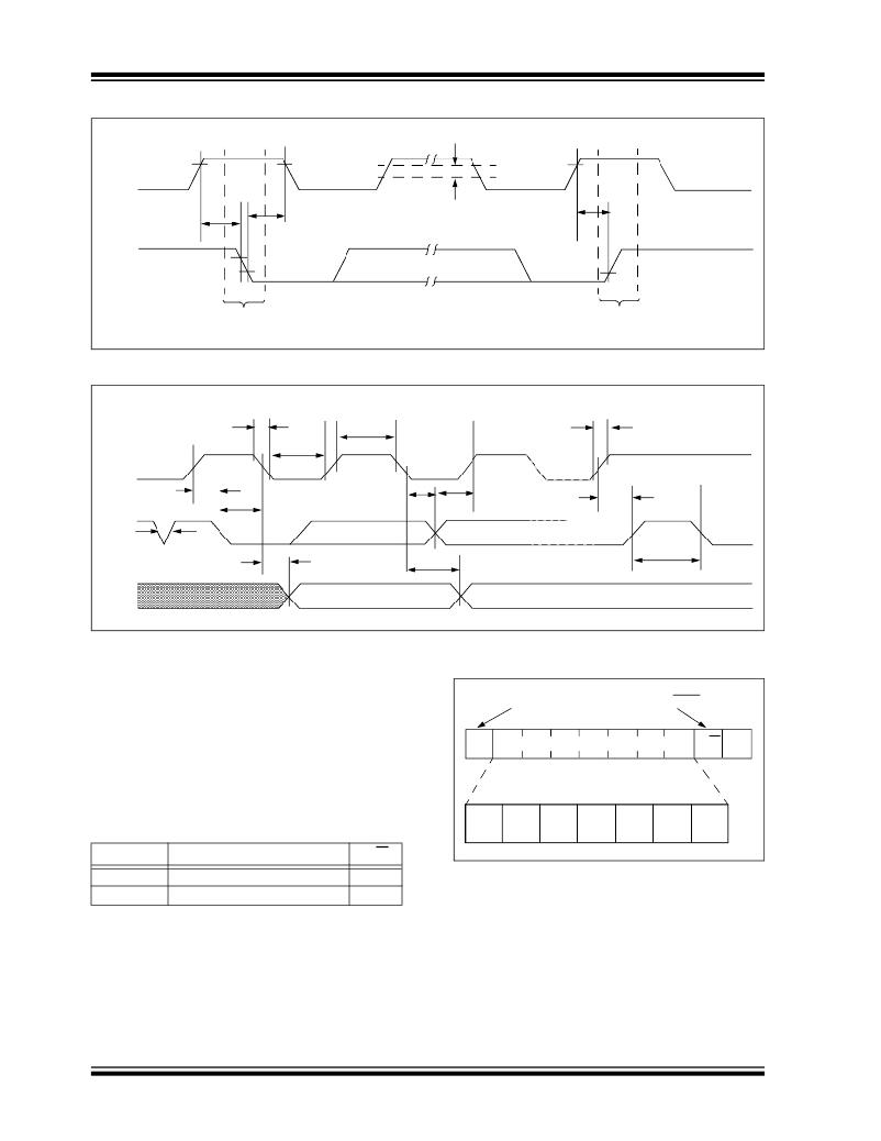
FIGURE 3-5:
SCL
BUS TIMING START/STOP
V HYS
SDA
T SU : STA
Start
T HD : STA
T SU : STO
Stop
FIGURE 3-6:
BUS TIMING DATA
SCL
T F
T LOW
T HIGH
T R
T SU : STA
T HD : DAT
T SU : DAT
T SU : STO
T HD : STA
SDA
IN
SDA
OUT
T SP
T AA
T AA
T BUF
3.1.6
SLAVE ADDRESS
FIGURE 3-7:
CONTROL BYTE
After generating a Start condition, the bus master
transmits the slave address consisting of a 7-bit device
ALLOCATION
code ( 1010000 ) for the 24LCS22A.
The eighth bit of slave address determines whether the
Start
Read/Write
master device wants to read or write to the 24LCS22A
Slave Address
R/W
A
(Figure 3-7).
The 24LCS22A monitors the bus for its corresponding
slave address continuously. It generates an
Acknowledge bit if the slave address was true and it is
not in a Programming mode.
1
0
1
0
0
0
0
Operation
Read
Write
DS21682E-page 8
Slave Address
1010000
1010000
R/W
1
0
? 2009 Microchip Technology Inc.
发布紧急采购,3分钟左右您将得到回复。
相关PDF资料
24VL014/SN
IC EEPROM 1KBIT 400KHZ 8SOIC
24VL014H/SN
IC EEPROM 1KBIT 400KHZ 8SOIC
24VL024/SN
IC EEPROM 2KBIT 400KHZ 8SOIC
24VL024H/SN
IC EEPROM 2KBIT 400KHZ 8SOIC
25A512-I/ST
IC EEPROM 512K SPI BUS 8TSSOP
25AA020A-I/MS
IC EEPROM 2KBIT 10MHZ 8MSOP
25AA02E48-I/SN
IC EEPROM 2KBIT 10MHZ 8SOIC
25AA080C-I/MS
IC SRL EEPROM 1KX8 1.8V 8-MSOP
相关代理商/技术参数
24LCS22A-I/PG
功能描述:电可擦除可编程只读存储器 VESA E-EDID Lead Free Package RoHS:否 制造商:Atmel 存储容量:2 Kbit 组织:256 B x 8 数据保留:100 yr 最大时钟频率:1000 KHz 最大工作电流:6 uA 工作电源电压:1.7 V to 5.5 V 最大工作温度:+ 85 C 安装风格:SMD/SMT 封装 / 箱体:SOIC-8
24LCS22A-I/SN
功能描述:电可擦除可编程只读存储器 VESA E-EDID RoHS:否 制造商:Atmel 存储容量:2 Kbit 组织:256 B x 8 数据保留:100 yr 最大时钟频率:1000 KHz 最大工作电流:6 uA 工作电源电压:1.7 V to 5.5 V 最大工作温度:+ 85 C 安装风格:SMD/SMT 封装 / 箱体:SOIC-8
24LCS22A-I/SNG
功能描述:电可擦除可编程只读存储器 VESA E-EDID Lead Free Package RoHS:否 制造商:Atmel 存储容量:2 Kbit 组织:256 B x 8 数据保留:100 yr 最大时钟频率:1000 KHz 最大工作电流:6 uA 工作电源电压:1.7 V to 5.5 V 最大工作温度:+ 85 C 安装风格:SMD/SMT 封装 / 箱体:SOIC-8
24LCS22AT-I/SN
功能描述:电可擦除可编程只读存储器 VESA E-EDID RoHS:否 制造商:Atmel 存储容量:2 Kbit 组织:256 B x 8 数据保留:100 yr 最大时钟频率:1000 KHz 最大工作电流:6 uA 工作电源电压:1.7 V to 5.5 V 最大工作温度:+ 85 C 安装风格:SMD/SMT 封装 / 箱体:SOIC-8
24LCS22AT-I/SNG
功能描述:电可擦除可编程只读存储器 VESA E-EDID Lead Free Package
RoHS:否 制造商:Atmel 存储容量:2 Kbit 组织:256 B x 8 数据保留:100 yr 最大时钟频率:1000 KHz 最大工作电流:6 uA 工作电源电压:1.7 V to 5.5 V 最大工作温度:+ 85 C 安装风格:SMD/SMT 封装 / 箱体:SOIC-8
24LCS52/P
功能描述:电可擦除可编程只读存储器 256x8 - 2.5V RoHS:否 制造商:Atmel 存储容量:2 Kbit 组织:256 B x 8 数据保留:100 yr 最大时钟频率:1000 KHz 最大工作电流:6 uA 工作电源电压:1.7 V to 5.5 V 最大工作温度:+ 85 C 安装风格:SMD/SMT 封装 / 箱体:SOIC-8
24LCS52/SN
功能描述:电可擦除可编程只读存储器 256x8 - 2.5V RoHS:否 制造商:Atmel 存储容量:2 Kbit 组织:256 B x 8 数据保留:100 yr 最大时钟频率:1000 KHz 最大工作电流:6 uA 工作电源电压:1.7 V to 5.5 V 最大工作温度:+ 85 C 安装风格:SMD/SMT 封装 / 箱体:SOIC-8
24LCS52/ST
功能描述:电可擦除可编程只读存储器 256x8 - 2.5V RoHS:否 制造商:Atmel 存储容量:2 Kbit 组织:256 B x 8 数据保留:100 yr 最大时钟频率:1000 KHz 最大工作电流:6 uA 工作电源电压:1.7 V to 5.5 V 最大工作温度:+ 85 C 安装风格:SMD/SMT 封装 / 箱体:SOIC-8
